Carbon equivalent describes how a cast iron composition behaves during solidification. It is not simply a chemistry number — it is a prediction of fluidity, shrinkage, and structure. Thermal analysis lets a foundry read that prediction from the melt itself.
What carbon equivalent means
In cast iron, carbon and silicon both promote graphitisation and lower the effective carbon content. The carbon equivalent (CE) combines them into a single value, typically expressed as:
CE = %C + (%Si + %P) / 3
The formula is a simplification, but it is a useful one. A low CE tends toward a more strongly chilled, carbide-prone structure. A high CE improves fluidity but can increase the risk of graphite flotation and shrinkage porosity. The target window depends on the casting section, the mould, and the intended grade.
Why measure CE in the melt
Calculating CE from a spectrometer result is useful, but it assumes the sample represents the melt and that the chemistry is final. Thermal analysis measures the cooling behaviour of a sample poured from the melt, so it captures the combined effect of composition and condition at that moment.
That makes it a fast process check. The operator can see whether the heat is inside the window before pouring, rather than discovering the problem after the castings are opened.
Reading the cooling curve
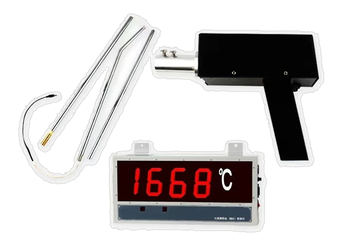
A thermal analysis cup contains a thermocouple. When the melt is poured into the cup, the system records temperature against time as the sample cools and solidifies. The shape of the curve reveals several features:
- Liquidus arrest: the point where primary austenite or graphite begins to form.
- Eutectic arrest: the region where the remaining liquid solidifies.
- Recalescence: the temperature rise after nucleation, which carries information about nucleation and undercooling.
- Solidus: the end of solidification.
Software can translate these features into carbon equivalent, carbon, silicon, and nodularity indicators. The numbers are only as good as the cup, the thermocouple, and the sampling technique, so consistency matters.
Thermal analysis is not a replacement for chemistry
Thermal analysis is fast and process-oriented. It does not tell you the full alloy composition, and it should not be expected to replace spark OES or combustion analysis. The strongest workflow combines them: OES for element-by-element chemistry, thermal analysis for the melt's solidification behaviour, and combustion analysis for critical carbon and sulfur confirmation.
Where it fits in the routine
- Take a representative sample from the melt.
- Measure the base chemistry with spark OES.
- Pour a thermal analysis cup and record the cooling curve.
- Compare carbon equivalent and temperature with the target window.
- Adjust the heat or proceed to pouring.
- Record the result against the heat number.
The value of the routine is not the number on the screen. It is the decision it enables: pour, adjust, or hold. A foundry that records the result but does not act on it has added a step without adding control.
Common sources of error
Thermal analysis is sensitive to sample handling. A wet or cold cup, a damaged thermocouple, a non-representative sample, or a delay between sampling and pouring can all distort the curve. Treat the cup as a measurement device, not a disposable afterthought, and check the system against known reference samples.
As with any process instrument, the operator matters. A short training session on sampling, cup handling, and curve interpretation often improves results more than a hardware upgrade.
Common questions
Is thermal analysis the same as a spectrometer?
No. Thermal analysis measures the cooling and solidification behaviour of the melt and can estimate carbon equivalent and related values. A spectrometer measures elemental composition directly.
Can thermal analysis measure carbon and silicon?
Some systems provide carbon and silicon estimates from the cooling curve. These are useful for process control but should be interpreted alongside direct chemistry results.
How often should a cup be changed?
Use the cup according to the manufacturer's instructions and your process procedure. Damaged, damp, or contaminated cups should not be used because they can distort the cooling curve.
Published by YuBoo Application Engineering
Share by email